"How To....."
Dual Circuit Brake Servo
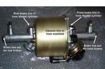
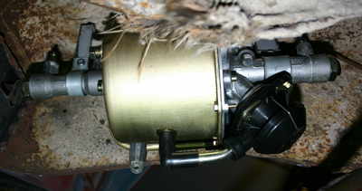
(April 04, 2011)Firstly, plumbing the servo. This image shows the correct pipework necessary for the servo.
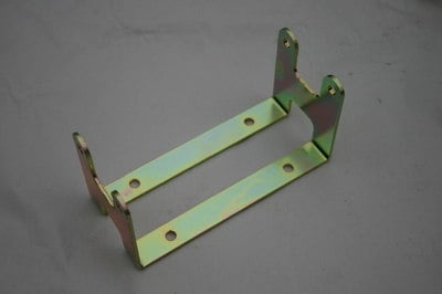
The new zinc coated brackets come pre-formed ready for use.
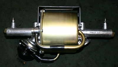
Remove the top pair of allen key fittings from each side and mock up the mounting bracket onto the servo.
Once the bracket & servo are mocked up, offer the unit up to the chassis & mark its mounting location. Just ahead of the front chassis cross member works well on both LHD & RHD models.
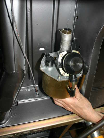
Once marked, remove the bracket from the servo & place against your marks. Centre punch the mounting holes to the cab floor. Before drilling these holes, make sure the spare wheel space and tool locker is empty. Drill through the panel and either bolt the mount in position with nyloc or rivnuts. (image shows different hanging mounts). A spot of thread lock will add extra protection from the mounting bolts working loose. Now you have the mount securely bolted to the chassis, refit all the allen key fittings, again with a spot of thread lock and plumb the servo into your master cylinder & brakes.
The forward most port on the m/c is connected to the rear circuit on the servo.
The rearward most port on the m/c is connected to the front circuit on the servo.
The brake pipe out of the servo for the front brakes requires a T-piece to split to each front brake.
The brake pipe out of the servo for the rear brakes needs to be routed to the T-piece that is factory installed on the rear frame horn.
Where brake pipes or vac' hose pass through bodywork & chassis sections, rubber grommets should be used. These are available through the webshop.
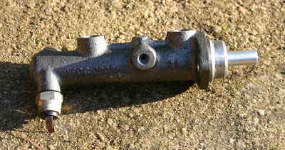
As the servo's are dual circuit, early split screen vans require the master cylinder upgrading to dual circuit also.
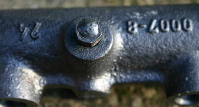
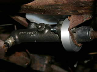
Dual circuit master cylinder used in the conversions. One of the outlet ports need blocking. Either fit an M10 bung to seal the port or weld up an old brake union fitting.
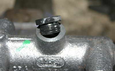
Moisten the bungs between the res' & master cylinder with brake fluid, push bungs into the master cylinder then press res' fully home into the master cylinder.
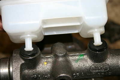
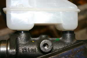
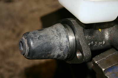
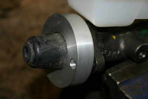
Now is a good time to ensure the adjustment nut & thread on the m/c push rod are free. Fit the rubber boot, then ally spacer & bolt the master cylinder to OG mounting bracket. Now adjust the pushrod for the correct clearance. Factory spec' states 1mm of free play. CSP's instructions states 3/8" free play.
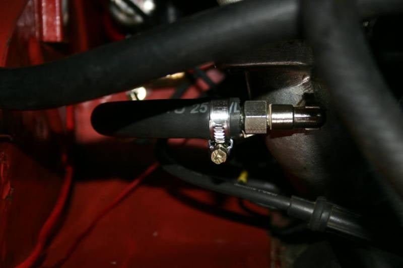
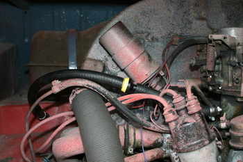
A vacumn connection is required to the manifold. The following images show twin manifolds or single carb' engines tapped & threaded with 1/8 BSP.
A non-return valve is supplied in the bundle kit to prevent fuel vapour making its way to the servo.
Choose a location on your specific manifold that does not effect the accel' linkage or any other components.
Then finally bleed the brakes as per normal.
